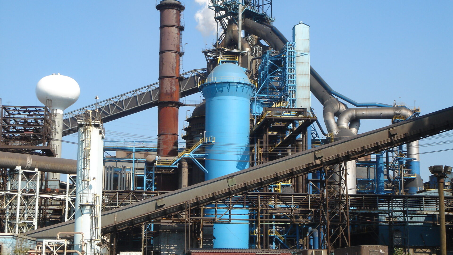
Why, when and how to build your fourth stove?
A significant part of today’s blast furnace hot blast systems have been in operation for decades. Due to their age, the condition of the equipment must be monitored closely. More frequent inspections, preventive corrective actions and campaign extension measures are necessary to assure the safety, reliability and availability of the plant.
Structural improvements can be triggered by various reasons, such as increasing plant capacity, deteriorating performance, reliability issues and stricter norms (safety, emissions). A major hot blast system upgrade should be incorporated in the plant’s long term strategy planning, considering plant capacity, campaign lifetime targets, blast furnace reline plans, etc.
Depending on the circumstances, constructing a new stove can help to increase capacity or minimize production losses while the existing stoves and related equipment are upgraded to the featured specs and complying to the latest industry norms by introducing the latest stove design developments. The design of the stove primarily depends on the plant lay–out and owner’s preference, since performance and reliability differences between the various modern stove designs are marginal. Related CapEx differences are primarily the result of project approach and execution instead of stove design concept.
This article was presented during the ABM Week in 2023 in São Paulo, Brazil.
INTRODUCTION
The blast furnace is a major contributor to CO2 emissions in a steel plant. Many steel plants are working on long term zero–emission strategies that include replacement of the coal–based BF–BOF route by hydrogen– and electricity based ironmaking technologies with DRI–units in combination with smelters and/or EAFs. This poses the question if investments for improvements in the blast furnace plant equipment other than regular maintenance efforts (to guarantee the safety of the equipment) and like–for–like repairs (to assure reliability of the plant) can be justified and implemented with a reasonable pay–back time.
The hot blast system has always been a critical component in blast furnace operations. Failure of a stove or reduced stove capacity as a result of checker degradation will directly affect blast furnace production and efficiency. Many blast furnaces have been built decades ago and since the moment of commissioning, the hot blast system has been exposed to high temperature– and cyclic operation 100% of the production time. Consequently, gradual refractory degradation phenomena and mechanical components fatigue can become a risk in terms of safety, reliability and heating capacity.
Ultimately, plant management faces a choice: continuing operations with progressively increasing maintenance effort, reduced efficiency and loss of production or investing in equipment. Danieli Corus has developed an integrated campaign management approach (Van Straaten et al, 2019) that schedules these activities such that the system will meet – as part of the overall blast furnace plant strategy – the desired campaign duration while delivering the required amount of hot blast at minimum cost and minimum risk (see Figure 1).
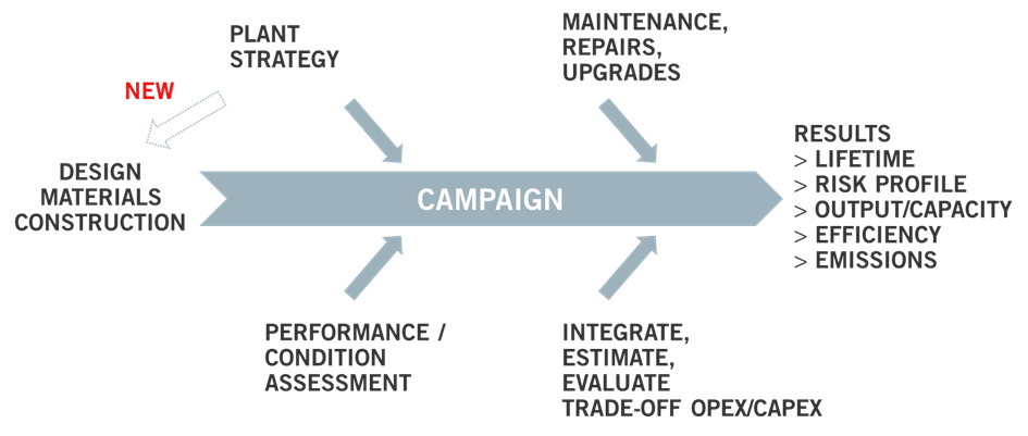
Figure 1 – Systematic Campaign Management Approach
DEVELOPMENT
Basis for the campaign management program are the hot blast system performance requirements, which are defined using a comprehensive “Cost of Hot Metal” process model that takes into account heat and mass balance calculations, process scenarios and flow sheet configurations for upstream and downstream plant equipment to eliminate any potential over–specifying.
Secondly, the condition of the hot blast system mechanical components, equipment and internals as well as its process performance are assessed.
Finally, all available options for campaign extension are evaluated for their urgency, cost and contribution to a successful continued campaign.
A specific outcome may be the advice to install a new stove at an existing 3–stove hot blast system. Such new 4th Stove extension projects are typically “end of the line” solutions based on scenarios such as:
- Future hot blast capacity increase
- Severe stove condition degradation and as a consequence major (time consuming) reconstruction of the stoves. With one out of three stoves out of operation, blast furnace production and/or efficiency is affected significantly, which can be prevented by constructing a new 4th stove in advance of the repairs.
Assessment
The condition assessment conducted by Danieli Corus at the hot blast system equipment, that is critical for the performance, will take into account:
Process performance
This includes analysis of historical operating data and trends, “control room discussions”, evaluation of process control rules, waste gas measurements and pressure drop measurements. The actual hot blast stove performance is compared with the theoretical capacity using the Danieli Corus proprietary stove simulation model.
Mechanical components condition
Shell thickness measurements provide an indication for the amount of corrosion. Full penetration cracks are identified using ultra–sound and/or soap tests. Other methods to determine the condition of the shell are TOFD (time–of–flight diffraction) measurements for stress corrosion cracks, thermography or stress calculations based on actual norms and shell thickness.
Internals condition
Mapping the temperature by a thermographic survey and internal inspections using a water cooled endoscopic camera have proven their value to establish the refractory condition. Within a regular blast furnace maintenance stop, physical inspections are possible below the checker grid and ceramic burner (combustion gas and air inlet) if adequate safety measures are taken.
Lifetime extension strategy
For any of the disciplines Process, Shell and Internals, the corrective measures, improvements and strategic investments can be placed in a timeline following the overall plant strategy (see Figure 2), creating a road map of measures from programs for campaign extension to full hot blast system revamp solutions.
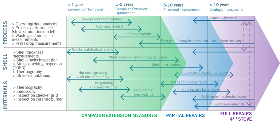
Figure 2 – Road map of measures, repairs and upgrades
Campaign Extension Measures
First priority for any plant owner is to keep the hot blast system a safe working environment. Continuous attention for cracks and hot spots and solving these at the earliest opportunity will prevent further degradation and extend the lifetime of internals and steel components. Examples are “online grouting” to mitigate hot spots and local shell reinforcements (bandages) in case of cracking at circumferential welds. Short term improvements, not directly related to equipment upgrades can be found in the manner of operating the Hot Blast system. Danieli Corus operating specialists can assist in objectively assessing and analyzing the process parameters and operating practices. Examples of improvements are blast time optimization, dome temperature stability and cold blast mixing valve setting. As a final phase of process fine–tuning, Danieli Corus stove optimization automation – one of the modules of the blast furnace level 2 system – is a valuable tool.
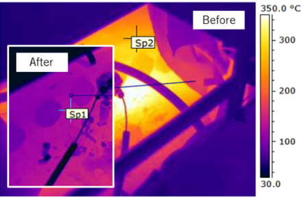
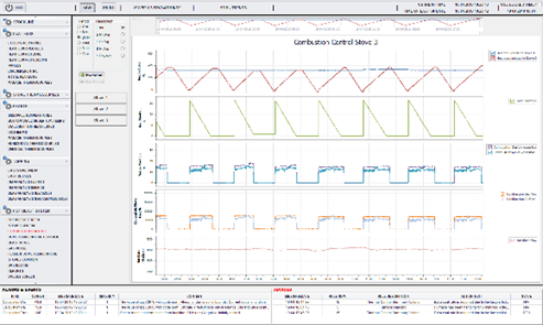
Figure 3 – Short term improvements, from left to right: online grouting and process optimization
Partial Repairs
Any repair can be triggered by either the outcome of an assessment – indicating progressive degradation of hot blast system components – and/or a strategic decision by plant management – for example aiming for hot blast system capacity or efficiency improvement. Medium term solutions consist of partial internal repairs, which can be executed – depending on the extent of the repair scope and circumstances – either in hot or cold condition. By incorporating the latest available technology – such as a new burner design, e.g. the “True Grid” burner developed by Danieli Corus – significant combustion efficiency improvements can be achieved, so that the stove is fit for purpose not only in terms of reliability, but also suiting future emission norms.
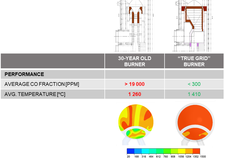
Figure 4 – Incorporating latest burner technology in partial stove repair project
For partial repairs, the total time that the stove is out of operation including cool–down and heat–up, depending on executing the project in hot– or cold condition, takes approximately 20 or 45 days, respectively. Because partial repairs are often executed in parallel with a blast furnace reline, loss of production is negligible. However, even when these partial repairs are carried out outside a major furnace stop, Danieli Corus studies indicated that the investment of a 4th stove could not be justified against the higher operating costs (coke penalty, loss of production) as a result of (temporary) two–stove operation.
Full Repairs
Any major shell repair should be considered in conjunction with the internals condition. As such, a double shell repair – to mitigate shell fatigue or stress corrosion cracking – is not sufficient if the refractories are in poor condition. In that case a partial shell replacement in combination with an internals upgrade may be the preferred solution resulting in lower cost of ownership in the long term.
A comparable situation occurs if the stove refractories show severe degradation. A full internals replacement project should not be executed without securing the shell condition for the same campaign lifetime. Based on a smart shell inspection program, the shell lifetime in different areas of the stove can be determined and a proper campaign extension and repair plan can be developed and executed as an integrated project together with the internals replacement.
Three recent Danieli Corus projects illustrate this philosophy. In the first project (Figure 5, left), the stove (one of four) had to be replaced primarily due to continuing and progressive shell cracking. Prior to the decision of replacing both stove shell and internals, the double shell option was abandoned since it was anticipated that the internals had to be repaired in due time as well.
For the other two projects, the poor condition of the internals triggered the renovation. Based on our shell assessment and recommendations, selected shell segments were replaced for the shell to match the lifetime of the new internals. In one case, an external combustion chamber stove was transformed to an internal combustion chamber arrangement, (partially) re–using the existing checker chamber (Figure 5, center). In the other case, the dome was converted to a “mushroom” design (Figure 5, right).
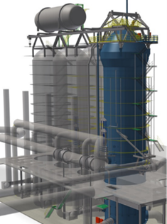
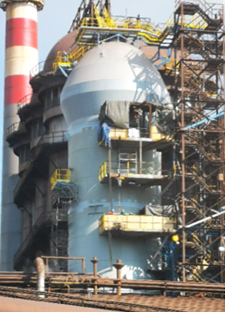
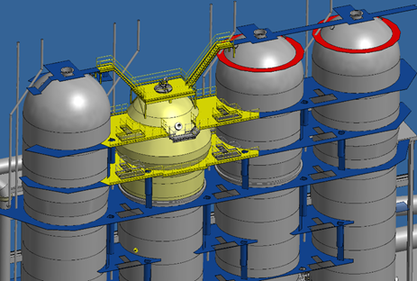
Figure 5 – Three stove renovation projects combining internals and (partial) shell replacement
The projects mentioned have in common that all of these hot blast systems consist of four hot blast stoves. With one stove out of operation – during the repair period of approximately 6 months – the systems can produce hot blast with three stoves, with limited loss of efficiency. Additionally, in such a configuration it is often complex to incorporate an additional – fifth – stove. That there are exceptions to this rule, is illustrated by the “5th” stove project that Danieli Corus executed at SSAB Oxelösund, described further in this article.
For the renovation of a three stove system, the choice of constructing a 4th stove is not an obvious one, either. In a study project for a plant in North America, Danieli Corus analyzed the feasibility of a suitable location, new connections and maintenance consequences of a fourth stove. In total nine scenarios were considered of which five 3–stove repair scenarios and four scenarios with a fourth stove. The scenarios were compared and evaluated based on several criteria, such as: hot blast capacity, lifetime expectancy, reliability, availability, efficiency, investment and – last but not least – production losses. The production losses for each scenario were determined by looking at the total construction time (demolition, shell repairs/replacement and internals replacement), partially overlapping with a scheduled blast furnace stop of four months. The duration of 2–stove operation (and related production losses), excluding the blast furnace reline period, ranged between 3 and 8 months (see Figure 6).
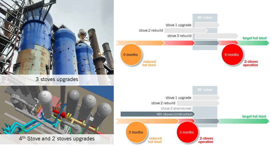
Figure 6 – Comparison of 3 stoves upgrade with 4th stove and 2 stoves upgrade
Comparing the investment, loss of production and – in this particular case – the complexity of rearranging existing and installing new connections to facilitate the new stove – it was decided by the plant owner not to build a 4th stove. The existing three stoves were upgraded using a tailor–made scope for each stove. All stove mechanical burners were replaced by modern, high efficiency ceramic burners. Two of the stoves were transferred from spherical dome to mushroom dome and received all new internals. Based on the shell assessment, the shell of one of the stoves was completely replaced while for the other one the majority of the cylindrical section remained in place. For the first stove (smaller capacity, recently rebuilt), the cylindrical shell section was extended to bring the capacity in line with the other two stoves, the upper part of the refractory was replaced and the combustion chamber was reconstructed to suit the ceramic burner.
Fourth Stove Lay–Out, Design and Construction
As discussed, factors that can justify a 4th stove are very much plant–dependent. The decision to build a 4th stove focuses on the following aspects in particular:
- Hot blast system capacity increase
- Large repair scope of the existing stoves (poor overall condition)
- Site relies on single blast furnace for hot metal supply
- Strong market conditions
- Provisions for 4th stove space and connections
Before a decision to build a 4th stove is made, lay–out considerations should be evaluated. In modern plants, a future 4th stove is generally considered in the lay–out plan and routing of the process mains. In that case the location of the new stove and connections to the existing system is straightforward (see Figure 7).
In other, often older plants, the plot plan has evolved and densified in the decades of the existence. Additional equipment, to keep the plant up to date to modern efficiency and emissions standards, may have occupied space that could have been considered for a 4th stove (see Figure 8).
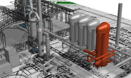
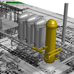
Figure 7 – Lay–out provision for 4th stove facilitates efficient construction
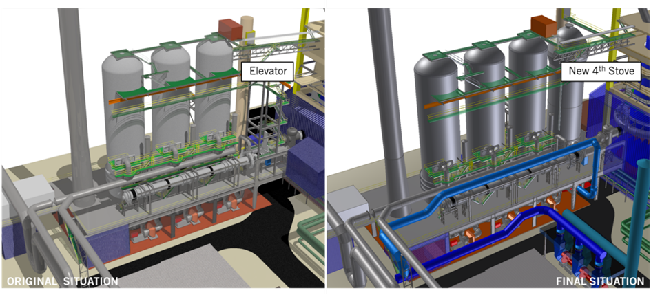
Figure 8 – No provision for 4th stove: complex construction plan
A second fundamental choice is the stove design concept (internal, external, dome combustion). This can be an in–kind solution to assure same capacity and minimal variations between all stoves. However, there are multiple arguments that suggest there are sometimes better solutions. The first is stove technology improvements, especially in the area of combustion technology and checker design. Considering normal campaign lifetime of stoves, the original stove design is at least 10–15 years old. Another point is that different stove concepts (especially external– and internal combustion chamber stoves) can be operated side by side, using the same control logic. Several examples can be found in the world, such as the Danieli Corus project of an internal combustion stove next to the original external combustion chamber stoves (Indiana Harbor Blast Furnace No. 7).
CASE STUDY: SSAB STOVE 47
The approach mentioned above, was largely applied in the decision–making process followed by SSAB for their new (5th) stove at Oxelösund that was built by Danieli Corus in 2019 (Van Straaten et al, 2021).
Project Scope
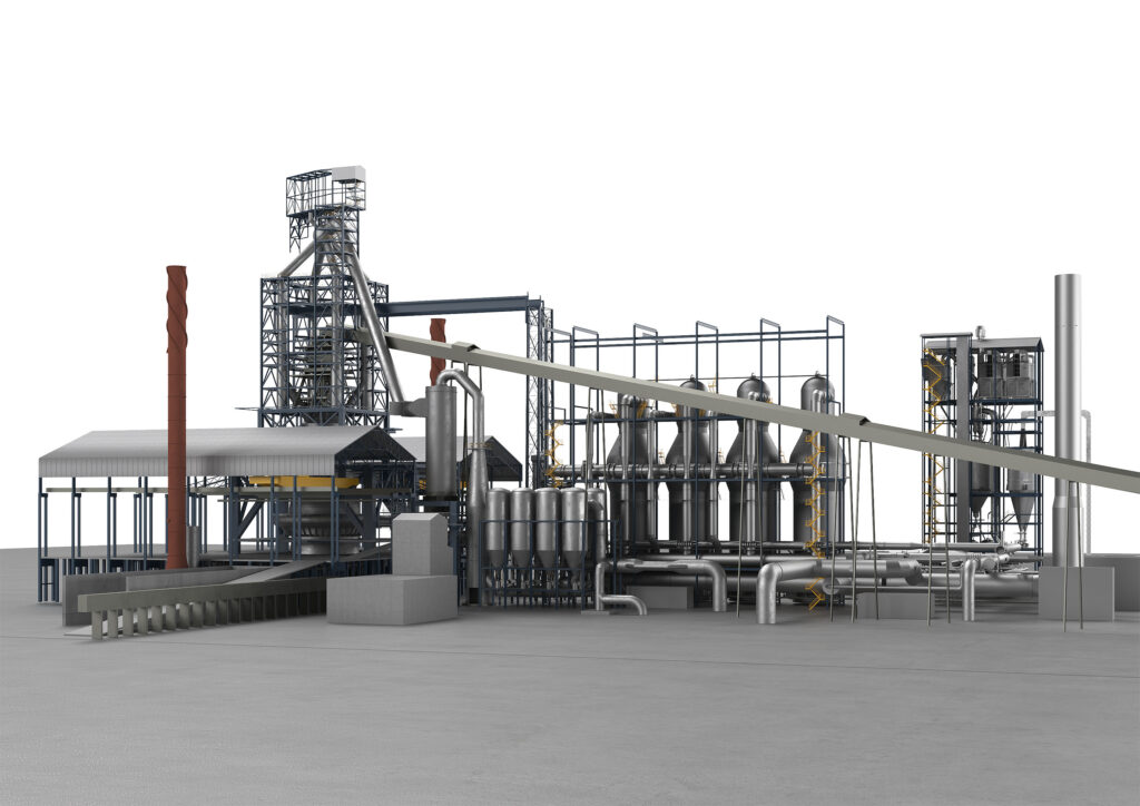
In 1961, Blast Furnace No. 4 was built with a hot blast system consisting of three stoves. With the declining performance of these three stoves over the decades, it was decided to add a fourth (stove 46) in 2014. Originally, the objective was to further modernize the hot blast system to three modern stoves, along with a preheater system (see Figure 9). Due to the adjusted long–term strategy – replacing the BF–BOF route by EAF steelmaking, this phase was never executed.
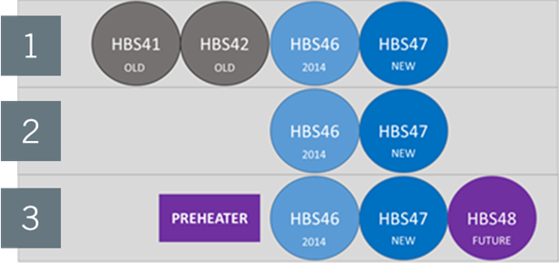
Figure 9 – Original long–term plan Oxelösund BF4 hot blast system
Points Of Attention
During the initial phase, specific project targets were defined for the system’s performance, campaign management strategy and on–site safety:
Combustion Performance
Stove 46, built in 2014, had been prone to vibrations originating from the burner and combustion chamber sizing. Based on process conditions such as combustion gas characteristics, the burner and combustion chamber of the new stove were duly designed for stable operations. Using CFD–analysis, the burner design was optimized for low emissions (CO and NOx) and high efficiency
Cost–effective solution
Considering the decarbonization program, the campaign targets for the new stove were limited to 15 years, requiring a “fit for purpose” design aimed for minimal maintenance, maximum accessibility of instruments and equipment.
Minimal impact on operations
To achieve the shortest possible interruption of hot blast supply, which applies to the extension of the hot blast main and tie–in to gas and utility systems.
With the stringent safety regulations in the proximity of the operating blast furnace, the project’s objective was to limit the installation effort on site to an absolute minimum.
Stove Design and Lay–Out
In order for the new stove to be integrated into the existing system, its diameter would have to be identical to that of the other stoves (7.2 meters) such that piping, platforms and all mains could be connected using the most straightforward arrangement.
Additional access to the top platform of stove 46 was created since this was only possible from the furnace–side via the older stoves. To facilitate the engineering, a full 3D scan of the existing situation was executed by SSAB such that all engineering work could be matched with the point cloud. As part of the engineering of the equipment, connection strategies for the ducting were developed – in particular for the hot blast main extension.
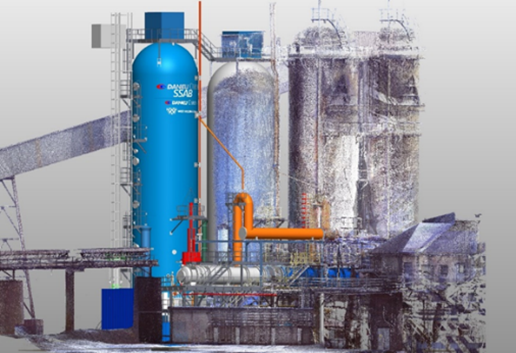
Figure 10 – 3D scan to match the new 4th stove extension with the existing system
The internals design was optimized for the 15 year campaign target. Instead of a free–standing “mushroom” dome design, a hemispherical dome shape was the “fit for purpose” choice. The larger burner and combustion chamber dimensions resulted in a slightly increased stove height compared to stove 46.
The refractory design further included all the Danieli Corus design features that allow for the long and secure campaigns widely embraced in our industry, such as a parabolic dome refractory arrangement, a gas–tight, well–insulated partition wall design to minimize the risk of bending and gas “short–circuiting” and the Danieli Corus–specific expansion allowances to prevent displacements and cracking (further reading: Niemeijer, 2001 and Van Stein Callenfels et al, 1998). A new burner crown design for improved mixing characteristics and stability was used for the free–standing burner and an additional protection wall was applied in the lower area of the combustion chamber for long term stability of the main walls.
Stove Shell Design & Construction Methodology
The stove vessel was designed for an operating pressure of 1.7 bar (g), using 16Mo3 shell material. To protect against inter–crystalline stress corrosion, flexible epoxy coating capable of withstanding high temperatures was applied.
Hot blast stove vessels are usually built using a ring–wise erection strategy. This practice is widely accepted but requires vast on–site efforts in terms of safety and quality within the boundaries of an operating blast furnace plant.
Pre–assembly and coating of the vessel in a workshop would allow a safer and more efficient fabrication and erection effort. While this approach is relatively common in e.g. the petrochemical industry, it is not widely accepted in the steel industry – with only an occasional single–piece erection of e.g. a gas cleaning cyclone on record. For this project, the plan was carefully evaluated by the end user, plant engineer and workshop. It was clear that the approach had many advantages:
- Improved “as built” quality
- Shell erection time on site reduced from 35 to 2 days
- Minimal interference with blast furnace operations
- Reduced safety risks (related to construction time, working on heights, scaffolding, hot works, working in confined space)
- Reduced construction management risks (related to shifts and delays in the project schedule)
The procedure would have to be duly prepared and pre–assessed extensively focusing on three main areas:
- Plant–wide commitment to the approach
- Transport route from workshop to foundation
- Crane capacity and lifting procedure
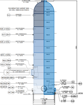
Figure 11 – Stove shell in segments vs one piece
Outside the plant, the route from the fabrication workshop to the nearest dock was assessed for load capability and the presence of railroad crossings, bridges, flyovers and overhead power lines. Earlier experiences of the mechanical workshop in Finland helped to clear all of these issues quickly.
At the SSAB site, a suitable landing for the barge with favorable routing towards the Blast Furnace No. 4 location could be selected. This route was assessed for overhead obstructions and particular care was taken to check load capabilities on and around railroad crossings and the presence of underground piping and cable tracks. In situ, a few potential lay–down areas were evaluated for their accessibility as well as their suitability for positioning the required cranes. An area at the west side of the furnace was nominated for its accessibility, the shortest transverse lift path and the possibility to prepare the area for the lift.
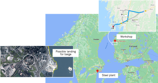
Figure 12 – Detailed planning of the route
The lifting contractor prepared a comprehensive crane plan, stipulating the crane requirement for the 100 tonne vessel given the elevation of the obstructions along the lift path and the required crane reach.
This comprehensive assessment of the transport route and detailed crane plan gave all parties the confidence that the procedure could be completed safely and secured the commitment of end–user SSAB, which was crucial for the project
Execution
The stove vessel was manufactured at West Welding in western Finland across the Baltic Sea in a workshop fully utilized for (semi–)automatic welding and surface treatment of large–scale pressure vessels. West Welding was selected for their track record in manufacturing such vessels for single–piece erection in other industries.
The industry–first of erecting a hot blast stove vessel as a single piece was made possible through a team effort with full commitment from the end user SSAB, West Welding as the vessel manufacturer, Viafin for on–site installation, crane contractor Havator and of course Danieli Corus in the role of plant engineer.
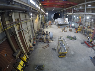
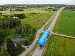
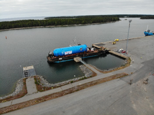
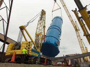
Figure 13 – Manufacturing, road transport, shipping and lifting of the stove shell
Before the arrival of the stove vessel at the Oxelösund dock, the lay–down area preparations as well as the removal of obstacles, excavations and civil works in the stove’s final location were completed by SSAB. Platforms connected to the existing hot blast system were modified to allow for further extension once the new stove 47 would be in place.
The vessel erection was completed within one working day. The joint project team kicked off with an extensive toolbox meeting to align schedules and procedures. The lifting procedure itself – from the vessel leaving its supports in the lay–down area to the initial fixation to the foundation bolts – was completed in less than two hours.
During the pre–shutdown phase, the hot blast stove internals (checker support, ceramic burner and refractories), the combustion air fan, the combustion gas downleg, the hydraulics room and platforms were installed. Final connections to the existing system were prepared, but completed only during a five–day shutdown. The hot blast main extension was prepared as a pre–assembled module for installation, including its refractory lining. The existing end cover was re–used. During the five–day shutdown, all the mains and ducting were connected.
The hot blast valve and the balance of the platforms and staircases were installed after the shutdown.
Operation and Performance
After the installation activities were completed, the new stove was heated up successfully as per the schedule required for silica refractories. The performance guarantee test was cleared.
The erection methodology has been a great success. The due preparation and assessment have been a worthy investment in a swift, efficient and above all safe erection phase. For future projects, feasibility of this methodology will be assessed for sites with suitable docks and relatively straightforward routing towards the final location. Single–piece erection of larger vessels is possible with the main constraint being accessibility (e.g. platforms) rather than crane capacity. Whenever such constraints would disallow this erection methodology, lifting the vessel in two or three pieces would be worth evaluating.
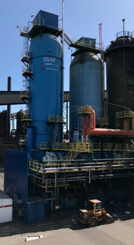
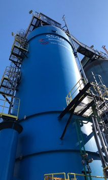
Figure 14 – The new 5th stove and mains extensions in place
CONCLUSION
Building a new 4th stove to an existing hot blast system may not seem to be a logical option within today’s “green steel” developments and announced blast furnace closures. However, it will take decades until the new technologies have been implemented widely. In the meantime, plant owners will remain responsible for low production costs (maximizing efficiency, minimizing maintenance effort and unplanned stops), target production levels (maximize availability) and comply to the latest safety and emission norms.
To achieve the same, continuous monitoring and regular assessments of an existing hot blast system will be required. It is important to align actual hot blast system performance with the long term production and efficiency targets of the plant owner and schedule appropriate actions pro–actively. Based on the observed condition, the owner can decide the direction: campaign extension by increasing preventive maintenance effort, partial repairs eliminating critical bottlenecks or a major overhaul for a second or third life of the system. Whenever such a major overhaul is decided for, the “fourth stove” scenario typically comes into play when:
- The capacity of the overhauled hot blast system is not expected to match the future hot blast requirements of the blast furnace ironmaking process
- The existing stoves have degraded to such an extent that operating with any two stoves during the overhaul of a third represents a risk or clear impossibility
- Overhaul requirement is so vast that the total duration of all repairs represent prohibitive cost connected to the efficiency losses of “n–1” operation.
Once a “fourth stove” scenario is chosen, it needs to be further defined technically in terms of equipment design and erection strategy. Whether the combustion chamber arrangement (external, internal) identical to or different from that of the existing stoves is selected will depend primarily on capital expenditure, process requirements and maintenance practices. Design details to be incorporated in the project’s engineering will be selected to match the process requirements as well as the required lifetime capability, to make the final design “fit for purpose”. Erections strategies based on larger, pre–fabricated modules or even single–piece vessels are particularly attractive for their efficiency and reduced on–site activity, but logistics and existing structures and infrastructure may be limiting or even prohibitive.
As illustrated with the SSAB reference project, a new stove can pay off even if the remaining time span of the blast furnace does not exceed 15 years. With an effective design and smart project approach the investments cost can be kept low, while the returns in terms of efficiency and production help to reduce the cost of hot metal.
REFERENCES
- Van Straaten, De Graaff and Engel. “Hot Blast System Development: Technology, Operations, Campaign Management.” 4th ESTAD (European Steel Technology and Application Days), Steel Institute VDEh. Düsseldorf (Germany), 24–28 June 2019.
- Van Straaten, Woltheus, Engel, Sarbrant and Willemsen. “New Hot Blast Stove 47 at SSAB Oxelösund – First ever stove vessel shell erected in one piece.” 5th ESTAD (European Steel Technology and Application Days), Jernkontoret. Stockholm (Sweden), 30 August–2 September 2021.
- Niemeijer. “21st Century Stoves for China – the World’s Largest Ironmakers.” 60th Ironmaking Conference, Iron & Steel Society. Baltimore, Maryland (USA), 25–28 March 2001.
- Van Stein Callenfels, Boonacker and Stokman. “Optimising Hot Blast Stoves for Extended Life.” Asia Steel 1998, pp. 53–57. Crambeth Allen Publishing, Hopesay (United Kingdom).

"*" indicates required fields
Hyundai Steel Dangjin Blast Furnace No. 3 Bosh Repair
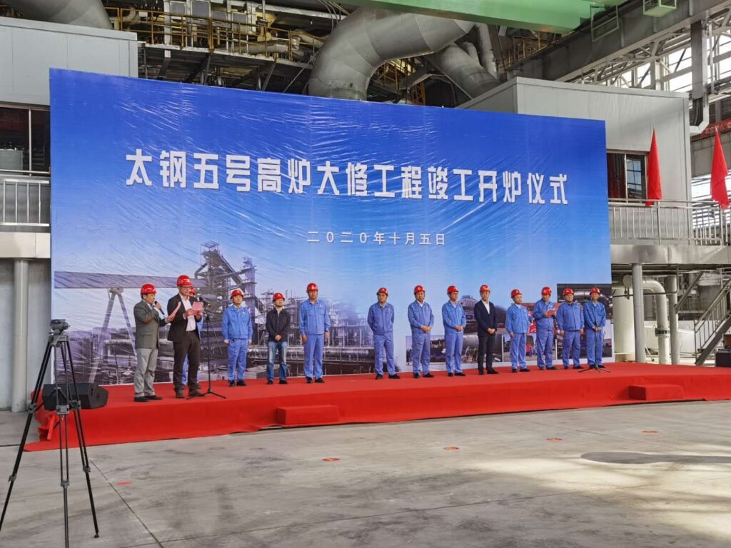
Shanxi Taigang Blast Furnace No. 5 Modernization
ArcelorMittal Nippon Steel India Greenfield Blast Furnace Nos. 2 & 3