Optimization of Dome Combustion Hot Blast Stoves using CFD Modelling
The dome–type, or top–gas/shaft–less, combustion hot blast stove (HBS) demonstrates superior performance over conventional internal and external combustion stoves due to its enhanced flame stability, higher combustion efficiency, precise flame control, and longer refractory life. This design is increasingly being adopted for the supply of hot blast air to blast furnaces, where maintaining a consistently high temperature is critical for the overall productivity of the ironmaking process.
Unlike conventional stoves that incorporate a vertical combustion shaft, the dome combustion configuration eliminates this component, thereby removing a significant structural and thermal limitation. The dome burner is equipped with tangential inlets that induce a strong swirl in the entering fuel–air mixture. This rotational motion facilitates enhanced mixing, increases turbulence intensity, and shortens the characteristic length and residence time required for complete combustion. The inherent swirl flow within the dome geometry promotes uniform heat distribution and reduces local hot spots, contributing to more stable flame behaviour and minimized refractory wear.
Nevertheless, the dome combustion system is not without challenges. Its operational reliability is closely linked to precise burner design, optimal fuel–air ratio control, and stable process parameters. Moreover, the structural complexity and sensitivity to thermal stresses can present design and maintenance constraints, necessitating careful engineering and robust process monitoring.
Visualization of the Combustion Process
To effectively address the design and operational challenges of DC–HBS, it is essential to visualize the internal flow and combustion processes. However, direct observation under operating conditions is infeasible due to the extreme thermal and chemical environment. Experimental setups are expensive and limited in their ability to replicate full–scale geometries and operational parameters.
Therefore at Danieli Corus, a comprehensive three–dimensional Computational Fluid Dynamics (CFD) model has been developed to simulate the coupled fluid flow, heat transfer, and combustion kinetics within the dome combustion system. This numerical model is customized for each project or design variant and incorporates key physical phenomena including low– and high–turbulence regimes, swirling flow dynamics, radiative heat transfer, combustion reactions,and flow through porous media (e.g., checker bricks). Achieving a fully converged steady–state solution typically requires approximately 36 hours of computation on a 12–core processor, reflecting the model’s complexity and resolution.
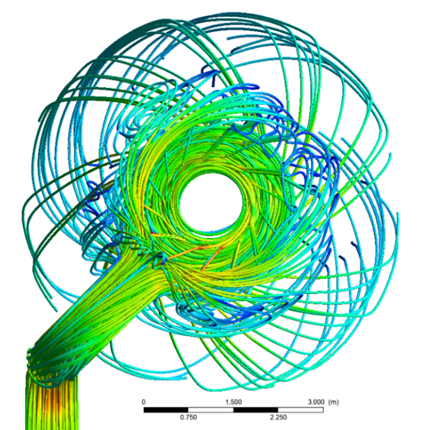
The CFD model has undergone iterative refinement over several design cycles. Through continuous validation, correction, and enhancement, it has evolved into a state–of–the–art predictive tool capable of resolving detailed internal flow features. As illustrated in Figure 1, the predicted velocity streamlines show strong swirl behaviour in the combustion region, which then expands smoothly along the dome walls through the expansion zone and ultimately enters the checker works region. The top–view clearly shows the absence of direct wall impingement by the flame, with flow instead swirling along the dome curvature, thereby ensuring thermal stability and structural integrity of the dome refractories.
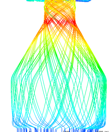
Figure 1 – Velocity distribution
Uneven temperature distribution
Figure 2 illustrates temperature and species distributions in various cross–sectional views:
- Horizontal planes from top to bottom
- Vertical mid–plane temperature
- CO mass fraction contours
From these visualizations, it is evident that the temperature field increases as the combustion products travel downward from the burner to the checker bricks. However, the temperature distribution remains non–uniform throughout the combustion chamber and persists into the checker zone, where no further chemical reactions occur. A critical observation from Figure 2c is the presence of residual carbon monoxide (CO), indicating incomplete combustion in specific zones. Ideally, a fully combusted mixture should contain negligible CO concentrations. Comparing Figures 2b and 2c, it becomes clear that regions with lower temperatures correlate with higher CO fractions. This inverse relationship underscores the importance of sufficient turbulence and temperature for complete combustion. Using CFD, such shortcomings in combustion performance were identified early in the design phase itself, prior to physical construction. The simulation results prompted further investigations to pinpoint the root cause, allowing targeted design modifications to improve combustion completeness, thermal uniformity, and overall performance of the hot blast stove.
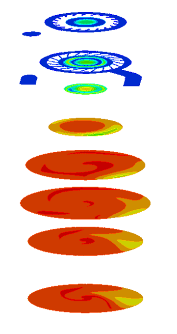


Figure 2 – Temperature and combustion products distribution
Root cause identification
Subsequent analysis reveals that the internal flow field within the dome combustion chamber is significantly non–uniform, contributing to inefficient combustion. As illustrated in Figure 3a, the carbon monoxide (CO) flow streamlines exhibit large separations or voids in certain regions [1], indicating under–utilized reactor volume and poor mixing conditions. These low–velocity zones result in incomplete combustion and lower thermal efficiency.
The root cause of this flow maldistribution is traced upstream to the burner inlet conditions. Figure 3b presents the fuel mass flow distribution through the tangential injection slots of the dome burner. The data shows considerable variation in fuel supply across the slots: those positioned directly opposite the main fuel inlet pipe receive disproportionately higher mass flow rates, whereas slots located farther from the inlet receive significantly lower flow. This asymmetry in fuel distribution disrupts the intended swirl pattern and contributes to non–uniform mixing of fuel and air. The resulting imbalance not only leads to combustion instability but also produces localized regions of high CO concentration and suboptimal temperature zones.


Figure 3 – CO flow lines and fuel distribution through the burner slots
Structural Optimization
The observed asymmetry in fuel distribution at the combustion chamber inlet is primarily attributed to the geometrical configuration: specifically the shape, size, and spatial arrangement of the inlet pipe, distribution chamber, and tangential slots. Since this asymmetry stems from the burner’s topology, a logical and effective solution involves structural or topology optimization of the burner system.
Topology optimization seeks to refine the burner geometry by systematically modifying key structural parameters to achieve a more uniform flow distribution. Several geometric variables such as slot orientation, slot spacing, inlet pipe offset, and the internal configuration of the distribution chamber can be iteratively adjusted to optimize flow symmetry and swirl intensity. Figure 4 demonstrates the outcome of one such optimized configuration. Compared to the base case, which adheres to a conventional burner design, the optimized version exhibits significantly improved fuel distribution across all tangential slots surrounding the combustion chamber. This enhanced distribution ensures more homogeneous mixing of fuel and air within the chamber.
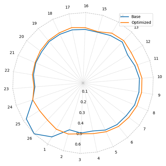
Figure 4 – Flow distribution through the fuel slots located around the combustion chamber
As a result, the combustion process becomes more stable and efficient, leading to reduced CO emissions, more complete combustion, and a more uniform and elevated temperature field. Figure 5 illustrates the resulting improvement in thermal uniformity and combustion efficiency. A quantitative comparison of key performance metrics including emission levels and final outlet temperatures between the base and optimized design is presented in Table 1. In optimized case, the temperature increases nearly 25 °C, while CO emissions are strongly reduced. Such an optimized burner indeed contributes for the decarbonization of industry both through the effective usage of fuels as well as through monetary yield in terms of energy savings.
Table 1 – The emissions and temperature level at the checker works inlet
| Base case | Optimized case | |||
| ave. | max. | ave. | max. | |
| CO [ppm] | 3937 | 28467 | 502 | 1585 |
| H2 [ppm] | 483 | 3810 | 32 | 84 |
| O2 % | 0.59 | 1.9 | 0.39 | 0.9 |
| CO2 % | 29 | 30 | 29.5 | 29.9 |
| T [°C] | 1400 | 1436 | 1425 | 1438 |


Figure 5 – Thermal field on the mid–plane for base case (left) and optimized burner (right)
Summary
CFD is employed in the dome combustion hot blast stove (HBS) design to overcome the limitations of direct observation and costly experimental methods under extreme operating conditions. Dome combustion offers improved flame stability, combustion efficiency, and refractory life, but faces design challenges such as flow maldistribution and incomplete combustion due to asymmetries in burner geometry. A detailed 3D CFD model simulates the complex physics involving turbulent swirling flow, heat transfer, radiation, combustion kinetics, and porous–media flow. The model enables visualization of velocity fields, temperature gradients, and species distributions, helping identify issues such as non–uniform flow and high CO emissions. By diagnosing root causes like uneven fuel distribution due to burner topology, CFD guides structural optimization of burner components (e.g., slot layout, inlet location). Optimized designs result in better air–fuel mixing, complete combustion, higher thermal efficiency, and lower emissions, well before physical implementation.

"*" indicates required fields
Hyundai Steel Dangjin Blast Furnace No. 3 Bosh Repair
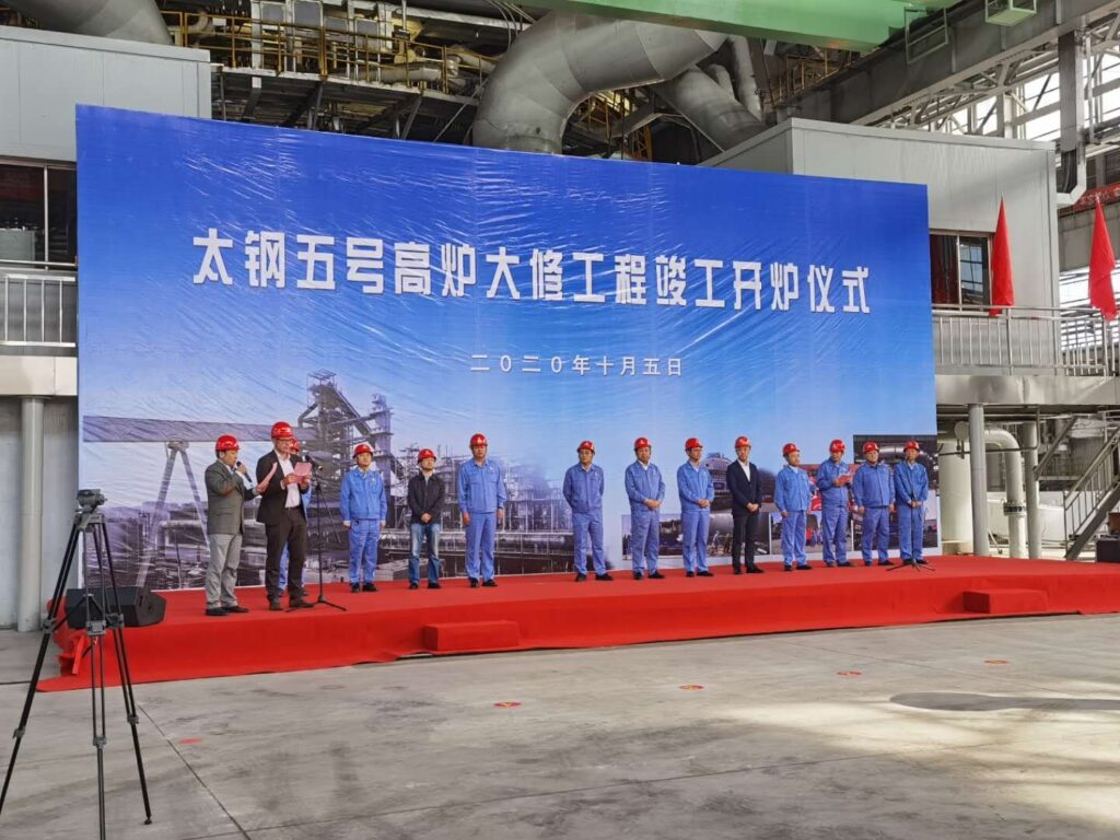
Shanxi Taigang Blast Furnace No. 5 Modernization
ArcelorMittal Nippon Steel India Greenfield Blast Furnace Nos. 2 & 3